Cable trays
In File > Environment > Systems and Lines, you can manage the Cable Tray lines as well as the Systems that these lines belong to. Your project environment can have one System or several Systems for cable trays—see Systems for examples. Add the required Cable Tray line definitions, so that designers can route cable tray parts using those lines.
Tip: You can also manage cable trays via File > Environment > All Library and Project > [project] > Cable Trays. New cable trays can be created via the Model Tree pane, as described in Managing tree items.
Adding cable tray lines to a system
-
In Plant Modeller, select File > Environment > Systems and Lines. If there is no suitable System for the cable trays you intend to add, first create the System.
-
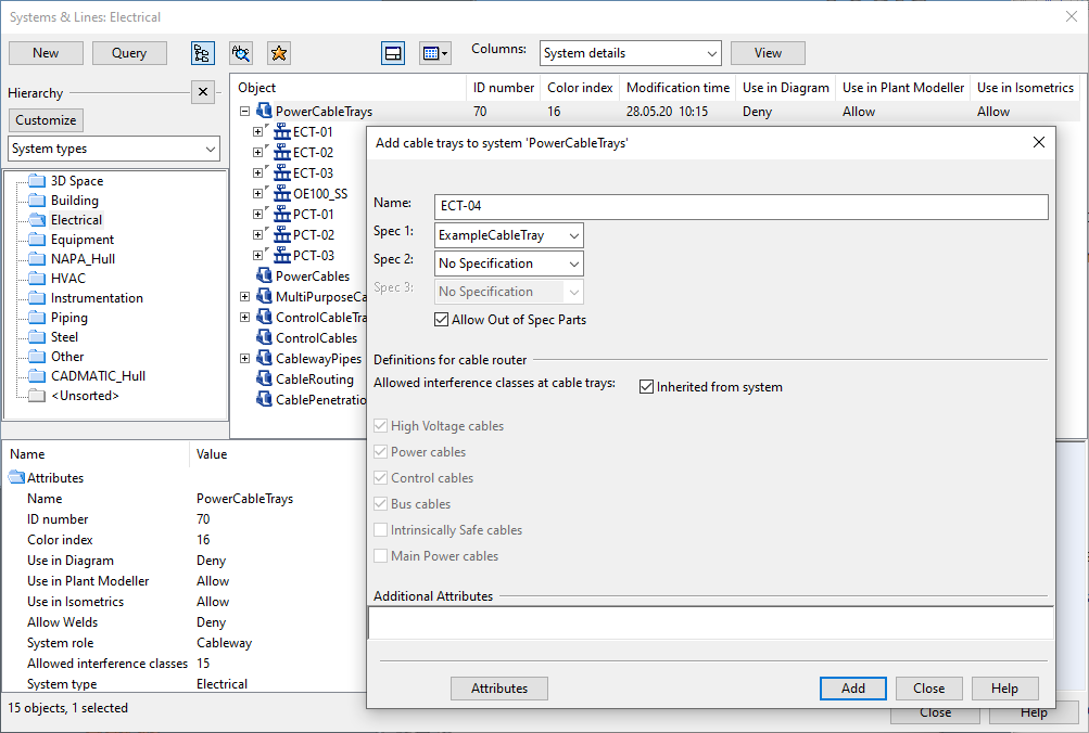
Right-click the System to which you want to insert the cable trays and select Add Cable Trays from the context menu. The Add cable trays to system '<name>' dialog opens.
-
Specify the cable tray properties:
-
Name
-
Spec 1–Spec 3 — Specifications that control component selection.
Select Allow Out of Spec Parts if the user is allowed to select also components that are not defined in the specifications.
-
Definitions for cable router – If Inherited from system is selected, the cable router gets the interference class settings of the cable tray from its System. Clear the option if you want to select a different set of classes from the list.
-
Additional Attributes – Additional information to be included in document output. Click Attributes to see the attributes that can be assigned to cable trays.
-
-
Click Add.
-
To add another cable tray to this System, repeat the steps 3–4. Otherwise, click Close.
-
In the Systems & Lines dialog, click Close.